![]()
 Home
Home Products
 Cameras
Launch Monitors
Cameras
Launch Monitors Software
 Enclosures
 ProTee
 E6 Courses
 Business
 Tech News
 View Cart
SCX Stereo Camera Calibration
Note that all below instructions assume that you are using CP version 10.0.4.4 or higher
available as of 01/26.2024
Please note: Other than scaling, calibration is only really intended for fine tuning.
If you are experiencing major ball carry discrepancies, then the cause most probably lies elsewhere.

In this case, check the above link.

Click the above button to see an easy and fast SCX calibration method
![]()
What is stereo camera calibration?
As each individual camera installation will be slightly different,
(i.e. cameras are mounted at different heights, different spacing, off-line and slightly skewed)
the main objective is to correct the factory set default calibration tables so that they match the particular users camera installation.
There are 4 parts to the calibration process
1.
Conversion of stereo camera disparity values to precise ball height off ground levels
2.
Camera alignment so that both cameras are tracking the ball in-line
3.
Camera perspective correction
4.
Scaling
i.e. converting distances measured in pixels - as the camera sees them - to real world distances mesured in cm
Please note that the easy method of camera calibration is now only recommended
Camera alignment instructions are dealt with on another page

Click above button to read more...
Scaling
The scaling factor is used to convert distances measured in image pixels (as the camera sees them)
to real world distances measured in cm.
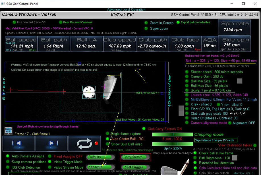
As a reference, the fixed diameter (42.67mm) of a golf ball is used.
In the above example, the ball size was measured at 50 pixels but the scaling factor of 0.1570 falsely converted the ball size to 78.50mm and not 42.67mm.
In this case, all distances will appear to be too long and thus ball and club speeds will be too fast
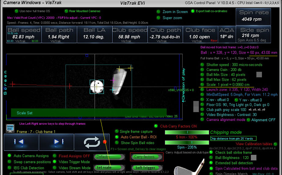
After setting the scaling factor correctly, ball and club speeds are correctly calculated
To set the scaling factor, place a ball on the mat and click the soft trigger in camera 1 panel.
Ensure that the ball has been correctly detected (as shown above with the aqua blue box lines around it)
and then just click the "Set Scale" button.
The scaling factor is then stored and shouldn't require any more adjustments.
Stereo camera Disparity explained
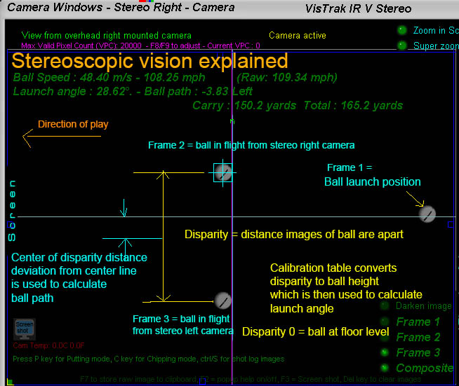
The above diagram explains the basic stereoscopic principles.
If the two 2 stereo cameras are aimed precisely at the center line and a ball is placed at floor level, the images of the will appear on top of each other.
The disparity of the ball is then zero (or near zero) and this is known as the "Converging point"
When the ball is elevated, the images of the ball in the camera frames will start to separate. The distance the ball images are apart is the "Disparity".
Using a "disparity to ball height" table, the exact height of the ball can be determined.
Knowing where the ball was before ball strike the ball LA and path can be determined.
Ball path is simply derived from the divergence the center of the disparity distance is from the center line.
i.e. a perfectly straight shot would show that the 2 ball images are the exact same distance from the center line.

![]()

![]()