![]()
Ball Spin Setup

![]()
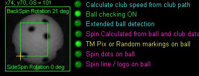
Selecting the Ball Spin Detection method
Please note:
Ball spin detection is now only performed with the system in TMPix or random dots/markings on the ball.
All other methods have now been removed.
Should the user's camera shutter speed setting be over 200 us, a warning will be displayed stating that
measured ball spin will not be possible due to motion blur.

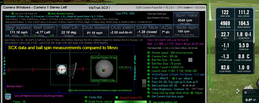
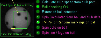
VisTrak SCX Ball Spin Detection
Random all around markings or Taylor made Pix balls method
Detecting spin from Taylor Made Pix balls
Current test results show that spin detection works best with the Taylor Made Pix balls
Main reasons are that
1. In contrast to using the ball logo, no matter what ball in flight frames are used to calculate the spin, there are always 2 frames showing the Pix images
2. In contrast to launch monitor proprietary balls with spin dots on them, TaylorMade Pix balls are readily available in any golf store for a regular ball price
![]()
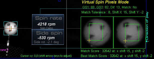
Measuring Ball Spin from an overhead ceiling mounted camera
using image pixel shift and rotation matching methods
Taylor Made PIX balls
This method consists of taking an array of pixel levels of the ball image in 2 adjacent frames
and obtaining a match with a series of pixel shifting and rotation procedures.
Using this method, rotation (and thus back and side spin) can be detected even with just a smudge mark on the ball.
i.e. this method is not looking for any specific dots or markings on the ball
so any ball can be used as long as there's something on the ball that is not pure white.
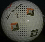
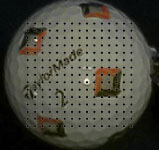
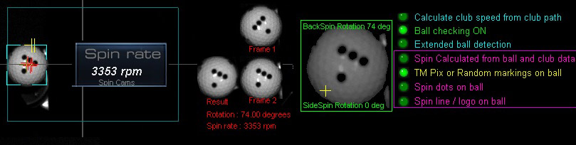
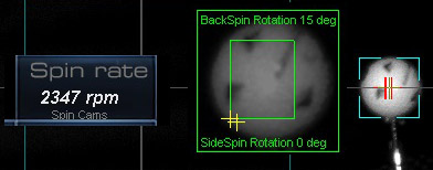
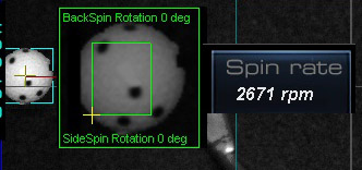
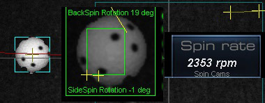
Low and high spin rate detection using TM PIX balls
![]()

Note that only well defined and spaced spin dot balls or balls with a strong logo can be used ( as shown above).
Note that camera exposure time (i.e. shutter speed) has to be set at or below 100 micro seconds and frame set to 1500 fps.
Lighting and shutter speed requirements
in order to measure ball spin with the ceiling mounted SCX
Measured ball spin requires clear non-blurry images of the ball in flight so that ball markings can be clearly seen.
This can only be accomplished by reducing the camera's exposure time to below 200 micro-seconds !
which in turn requires strong lighting.
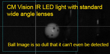
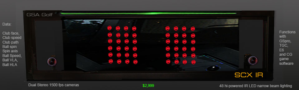
If not using the narrow beam IR lights (as featured in the SCX IR),
the system will have to feature additional lighting.
i.e. 4 LED track lights
 -
-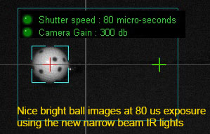
When using the CM Vision narrow beam angle lights, camera shutter speeds can be reduced to well under 100 micro seconds.
This will ensure that ball motion blur is at a minimum and ball markings are clearly visible
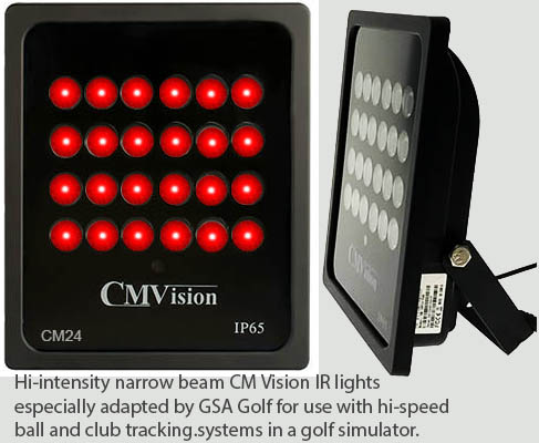
GSA Golf Hi-intensity CM Vision IR narrow beam lights
Track Lighting
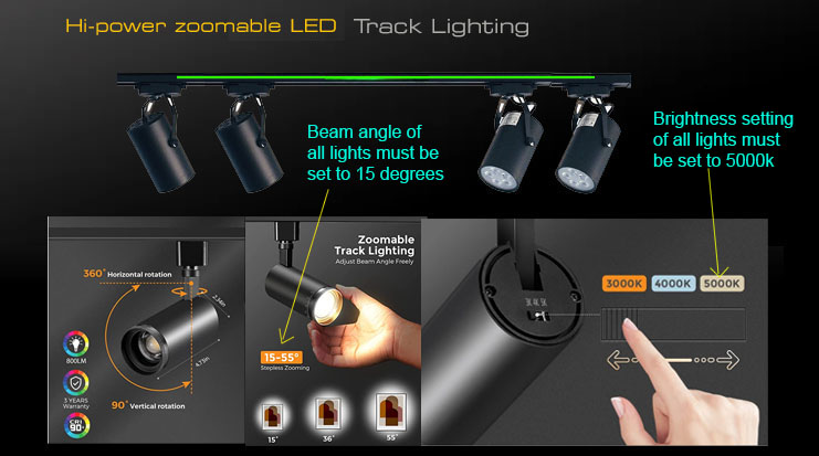
4 hi-power LED zoom-able track light system with 800 Lumens per light with track
IR Light spread over the hitting area
It is essential that the SCX or Eagle overhead unit is aimed such that the light is equally spread over the hitting area.
If using IR Light, you can use brown cardboard (use the box that the unit was shipped in for this)
placed over the hitting area to see the light spread with the SCX cameras running in video stream mode.
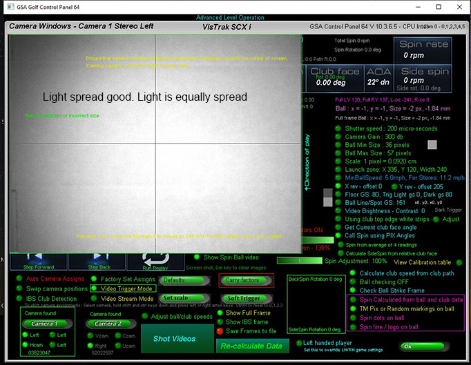

With the unit aimed such that the light is equally spread, then all balls in the hitting area
will appear bright and will be detected at 200 micro second shutter speed

if the unit is aimed away from the hitting area, then the light spread will not be equal
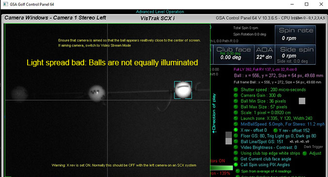
In this case, balls in the center of the FOV of the camera of left of it won't be detected and the system won't function.
Note that the VisTrak systems require that the camera shutter speed has to be at or below 200 micro seconds
if ball spin is to be measured and not calculated.
Side Spin
Note: When the system is unable to determine side spin from marked balls,
then side spin is calculated from the relative club face angle to path and not just from the face angle itself.

Examples:
1.Draw
If club path is 10 degrees in-to-out and face angle is 5 degrees open, then relative club face angle is -5 degrees closed
which results in a negative side spin and the ball will curve back left after starting off right (i.e. a draw)
2. Pull draw
If club path is 10 degrees in-to-out and face angle is -5 degrees closed, then relative club face angle is -15 degrees closed
which results in a negative side spin and the ball will curve left after starting off left (i.e. a pull-draw)
3. Push
If club path is 5 degrees in-to-out and face angle is 5 degrees open, then relative club face angle is zero degrees
which results in a zero side spin and the ball shot is a straight push right
3. Fade
If club path is 0 degrees and face angle is 5 degrees open, then relative club face angle is +5 degrees
which results in a positive side spin and the ball shot is a curve to the right after starting out straight
3. Push Fade
If club path is 10 degrees in-to-out and face angle is 15 degrees open, then relative club face angle is +5 degrees
which results in a positive side spin and the ball shot is a curve to the right after starting out right
VisTrak EVi / LX2
Ball Spin Detection from the Side camera
Note that no additional lighting is required with the LX2 and EVi (near) systems as the light source is very close to the ball
The default camera exposure time for the LX2 Vcam is just 50 micro seconds
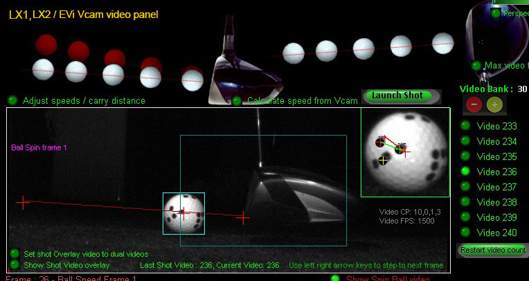
New spin detection method for side mounted camera systems (i.e. EV and LX)
The method consists of rotating ball spin frame 1 in single degree steps and comparing it to the ball spin image 2.
A best match test is performed which returns the amount of rotation between the two frames.
Knowing the amount of rotation and the time taken, accurate ball spin can be calculated.
Note that any ball markings can be used.
![]()
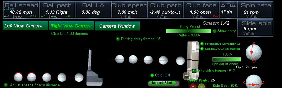
Ball spin for Putts
Measured ball spin when putting is done without the requirement to use ball markings.
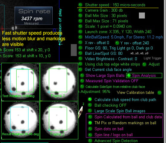
Spin Dot / Ball Logo Detection issues
In order to detect the spin dots on the ball or ball logos, the images should be sharp and clear.
In order to achieve this, the camera exposure time has to be fast (i.e. around 150 us) with bright lighting.
If the exposure time is too long (i.e. 300 us plus) then image blur will occur and the dots or markings
on the ball will appear faint or washed out.
![]()

Click above to read more about ball spin detectionn theory...
![]()
Ball Spin Adjustments
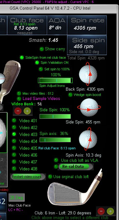
Use the spin slider bars in the "Shot Videos" panel to adjust all spin parameters.
Defaults are 100%
The sliders appear when moving the mouse over to the right side of the panel.
Note that back spin adjustments are separate for irons and woods
Click on the club image to select either an iron or a wood (drivers or Hybrids).
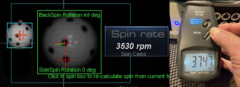
Ball Spin rate accuracy verification method
In order to verify the ball spin rate accuracy of the VisTrak SCX system,
we'll need a solid reference. i.e. frames of a spinning ball with a known spin rate.
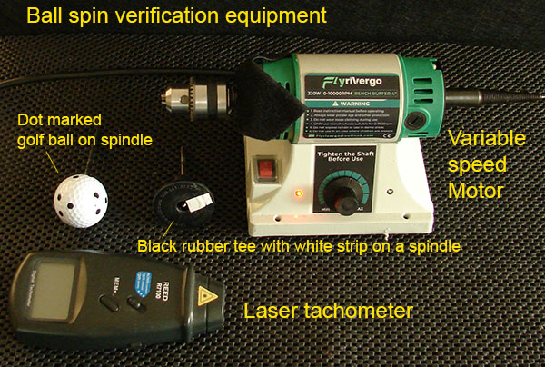
To do this, we used a variable speed DC motor with a marked golf ball on it.
First we'd have to accurately measure the spin rate of the motor.
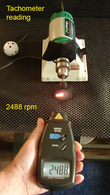
This was done by using a laser tachometer and a black rubber disc with a white strip on it attached to the motor's spindle.
In this case, the reading was 2488 rpm
Note that you can't use a tachometer with a golf ball because laser tachometers only read single white markings on a dark background.
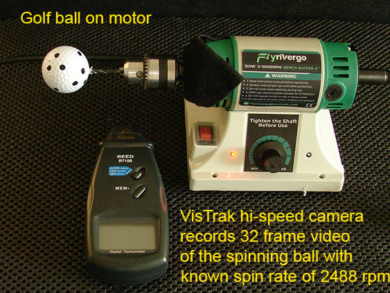
We then replaced the black rubber disc with a marked golf ball on the motor's spindle
and setup the VisTrak camera to capture 32 frames of the spinning ball.
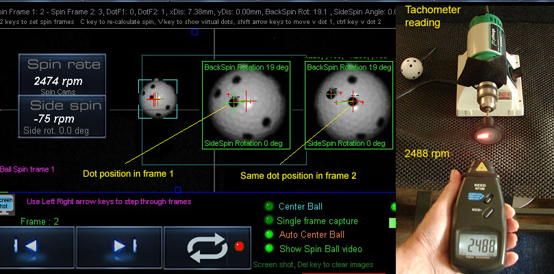
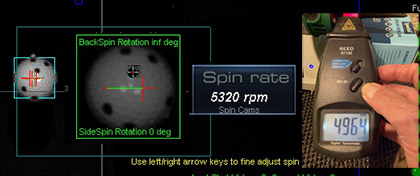
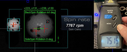
SCX Ball spin accuracy test results
 -
- -
-
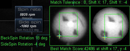
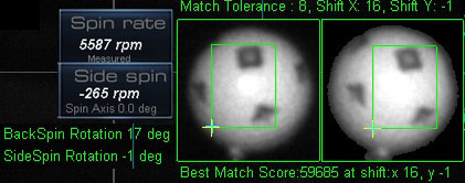
Spin detection using Taylor Made PIX balls
 --
--
The above two images show how the system detects the x and y marking pattern shift between 2 adjacent frames
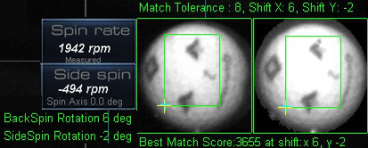
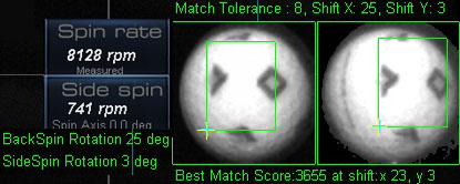
Spin detection using spin dot balls
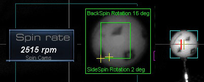
Calculated Ball Spin method
For those that - due to insufficient or incorrect lighting spread or are using balls without all-around clear markings on the ball -
the Calculated method of ball spin detection should be used.
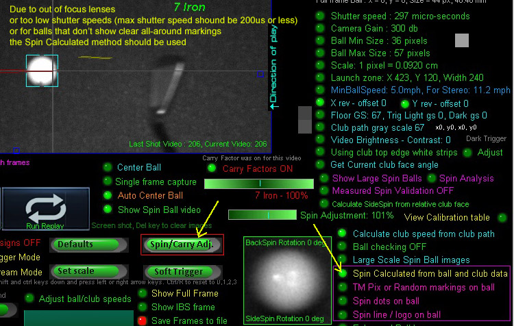
The above image shows blurry ball images and no detectable markings on the ball.
In cases like this, measured ball spin is not possible and the "Calculated" method of spin detection has to be used.
To adjust the calulated ball spin, click on the "Spin/Carry" adjust button.
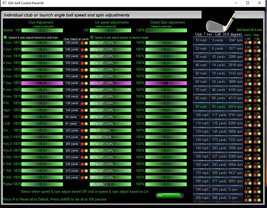
The Spin/Carry adjust panel allows you to adjust the calculated spin rates for all clubs separately.
In addition, spin rates can also be adjusted for individual ball speeds for a specific club too.
Use the small red and yellow buttons on the right side of the panel for this.
When adjusting, the resulting spin rates are automatically displayed for all ball speeds for the specific club.
Comparison Ball spin video playback images
with ProTee VX, Apogee and Uneekor QED
![]()
ProTee VX
$ 6,499
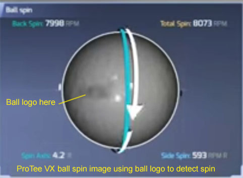
The ProTee VX is using the ball logo or any marking on the ball to detect spin
Even though the ball logo appears very faint, all test reports say the method produces very accurate spin rate detection
![]()
Uneekor QED
$ 7,000
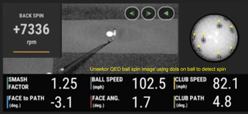
The Uneekor QED is using balls with dots on them to detect spin
The yellow dots show where the black dots on the ball were in the previous frame.
The distance and direction the dots move between frames is used to calculate the back and side spin rates.
![]()
TruGolf Apogee
$ 9,000
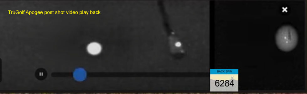
Based on the above Apogee low resolution post shot video playback image,
I have no idea how the Apogee captures all the club data (face angle, path and speed) using just one dot
plus all ball spin parameters (i.e. back and side spin)
![]()
GSA Golf VisTrak SCX
from
$ 1,699


![]()
 Home
Home Products
 Cameras
 Software
 Enclosures
 ProTee
 E6 Courses
 Tech News
 View Cart