![]()

![]()
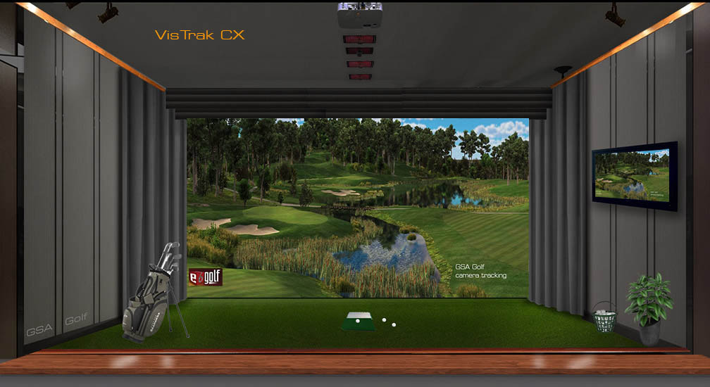
VisTrak CX
Operating, Setup and Installation Instructions
![]()
Mounting the VisTrak CX camera
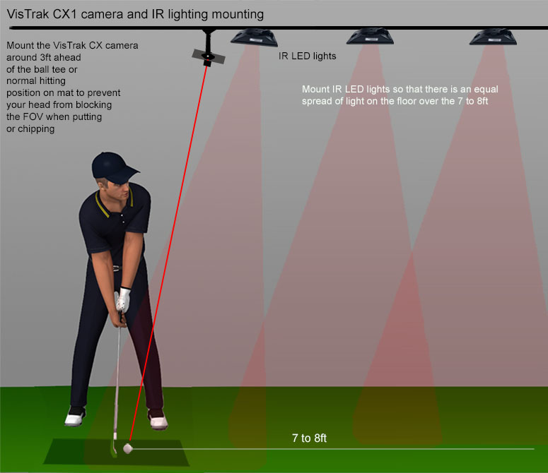
IR LED lighting
Note: If you have purchased the VisTrak camera without IR LED lighting, then the recommended IR lights are:
CM vision 200 IR Illuminators. Available on Amazon.
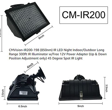
You'll probably require 2 to 3 of the CM-200s
![]()
PC requirements.
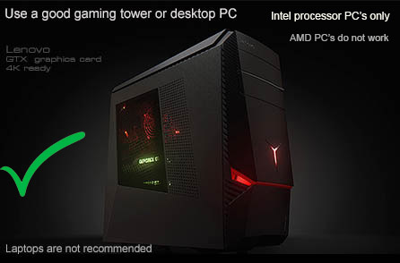
1. Intel i5 processor or higher
2. min 8GB RAM (16 GB recommended)
3. Nvidia 1070 Graphics card or higher or equivalent
4. Windows 10 - 64 bit
5. Internet Connection
Important ! USB 3 only

The VisTrak camera is a USB 3 camera and must be connected to a USB 3 port on your PC.
You can identify a USB 3 port by the SS symbol next to the port
The VisTrak hi-speed camera will require a PC that is capable of running hi-speed cameras.
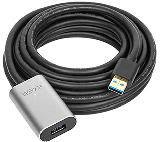
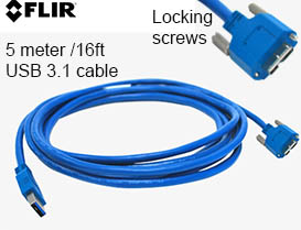
Current max VisTrak cable length is 16ft to 32ft
Warning! not all commercially available cables will work with the VisTrak camera
Use only the supplied cables or the ones shown above.
![]()
Installing the software
![]()
GSA Golf Game software download
Please note that software download links are now sent to you via email.
Contact us if you haven't received them
Note: If you encounter a windows error message stating that it could not find d3dx9_30.dll when starting GSA Golf,
download and copy the d3dx9_30.dll to your windows\SysWOW64 folder.
Download here d3dx9_30.dll
![]()
Installing the VisTrak CX Control Panel
GSA Control Panel (CP) full version download
Download and install your CP full version from the link supplied to you via email after purchasing a GSAGolf tracking system.
After you have downloaded and installed the full version GSA Control Panel,
download and install the latest GSA Golf CX Control Panel update
Click the below button to install the latest CX CP update
April 11 CX Control Panel update V 9.7.8.2
Lite update
April 11 CX Control Panel update V 9.7.8.2
Then click the above button to install the CX DLL camera driver files
Error message when first starting the CP ?
If you see the above error message when first starting the Control Panel (CP)
then your PC requires the VC Redistributable files.
Click on the above image to see an installation video
Download VC redistributables hereHere
![]()
Testing the camera
Close out the CP and connect the camera to the PC with the supplied USB 3 cables.
Ensure that the camera is connected to a USB3 port on your PC
Before starting the CP, wait until Windows has detected the camera.
The usual Windows "device detected" ding-dong sound will be played after a few seconds.
After restarting the CP, you should see a message on the CP's main window stating that the cameras are running.
What to do if the camera is not detected by the Control Panel
Start the windows Device Manager.
Locate the camera in the device list and double click on it.
Select "Driver" and then "Driver Details".
It should show that the "PGRUSBCam3.sys" is being used.
If not, go to this page:
![]()
Control Panel and Golf Game software
Note that 2 applications are run on the PC.
1. The Control panel (CP)
The CP controls the camera and processes the images. It is usually run in the background.
2. The golf game software (TGC, E6, RC etc)
The golf game software where you see the golf courses and the ball flying.
It is usually run in the foreground
![]()
VisTrak CX Principle of Operation
1. The ball is placed in the user defined Launch Zone area.
2. The camera will then look for the ball in this area.
3. Once the ball has been detected (an audible beep will sound) the camera will go into hi-speed image grabbing mode.
4. As soon as the ball moves (usually due to a ball strike) 4 to 5 frames are captured and the camera is put into idle mode.
5. Frame Image processing then determines where the ball is in each frame.
6. Calculations are then made to determine how far the ball moved and in what direction
Note: if the ball did not move out of the Launch Zone area, then it will be presumed that the user moved the ball position
and no valid shot will be generated. The system will then go back into "Looking for ball in Launch Zone " mode.
7. Horizontal ball speed and path is then calculated.
8. If the option "Measure ball launch angle from ball image size" is on,
calculations are made to determine the ball LA (launch angle).
If this option is switched off, then LA is derived from the loft angle of the club or the user defined LA of the club.
True ball speed is then calculated.
9. If the option "Measure club data" is ON, then club face, club path and club speed will the ejaculated from the frame images.
If OFF, then club data will be calculated from ball data.
10. Finally, the shot data is sent to the current golf game software running (i.e. TGC, E6 etc) so that the ball launches in the game.
Note that all these calculations are done very fast so that there is very little lag time between ball strike and ball launch in the game.
![]()
Setup window
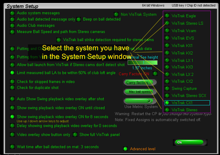
Before connecting the camera to the PC, start the Control Panel and click on Setup button.
Select VisTrak CX1 if using a single camera.
Select VisTrak CX2 if using 2 cameras.
Connecting the camera
Close out the CP and connect the camera to the PC with the supplied USB 3 cables.
Ensure that the camera is connected to a USB3 port on your PC
Before starting the CP, wait until Windows has detected the camera.
The usual Windows "device detected" ding-dong sound will be played after a around 30 seconds.
After restarting the CP, you should see a message on the CP's main window stating that the cameras are running.
Aiming the camera
Place a ball on the hitting mat surface.
Go to the camera window and right click on the "Deafults" button.
Click the Video Stream Mode radio button to start capturing images.
Aim the camera so that the ball appears in the center of the Launch Zone.
Lens focus
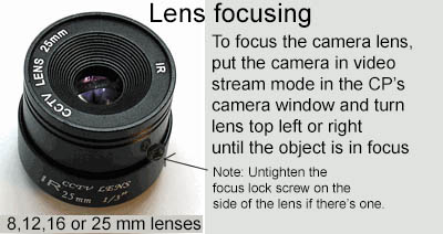
It is essential that the camera be focused as best as possible.
1. Place a ball on your hitting surface at the usual striking position
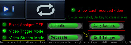
2. Click the Soft Trigger button to grab a new frame
3. If the ball appears not to be in focus - select the "Video Stream Mode"
4. Adjust focus by turning the camera lens focus dial back or forth.
You may require a second person either watch the screen or turn the dial.
Camera orientation and direction of play
Direction of play as seen in the Camera window is always right to left.

To confirm, place a club and any object above it in the FOV of the camera in the usual direction of play to help with orientation.
If you see the club facing the wrong direction or the club face reversed, you can use the "X and Y reversed" options to flip the image.
Soft Trigger to get a new image after every reverse action to confirm that all is correct.
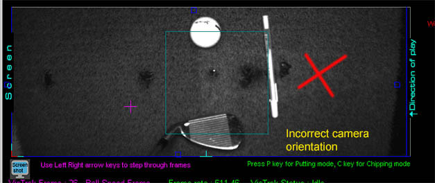
If you see that orientation is vertical (as in the above image) then the camera has to be rotated 90 degrees on its ball mount
Due to the camera pixel chip not being square, the frames or images cannot be rotated. Just flipped.
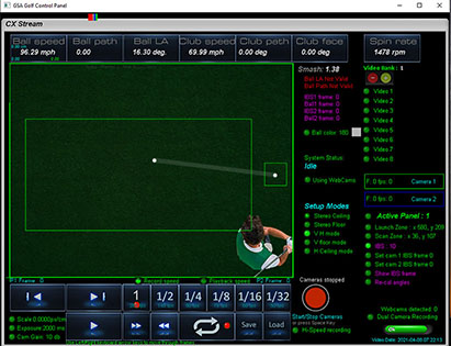
The CX1 camera lens is a 2.8mm wide FOV lens.
Direction of play in the camera images is always right to left.
![]()
Operating instructions
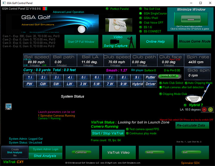
1. To start, either press the "Minimize Window" button or the "Start/Stop VisTrak" button in the CP's main panel.
The camera will then go into "Looking for ball in Launch Zone" mode.
2. Place ball in the Launch Zone area.
The camera will then go into "Ball detected. Waiting for Swing" mode.
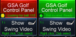
To better indicate to the player what status the CP is in, the overlay minimized CP window is colored.
When the system has detected the ball and is ready and waiting for the swing, the CP minimized window is shown in green.
Otherwise, it will be shown in red.
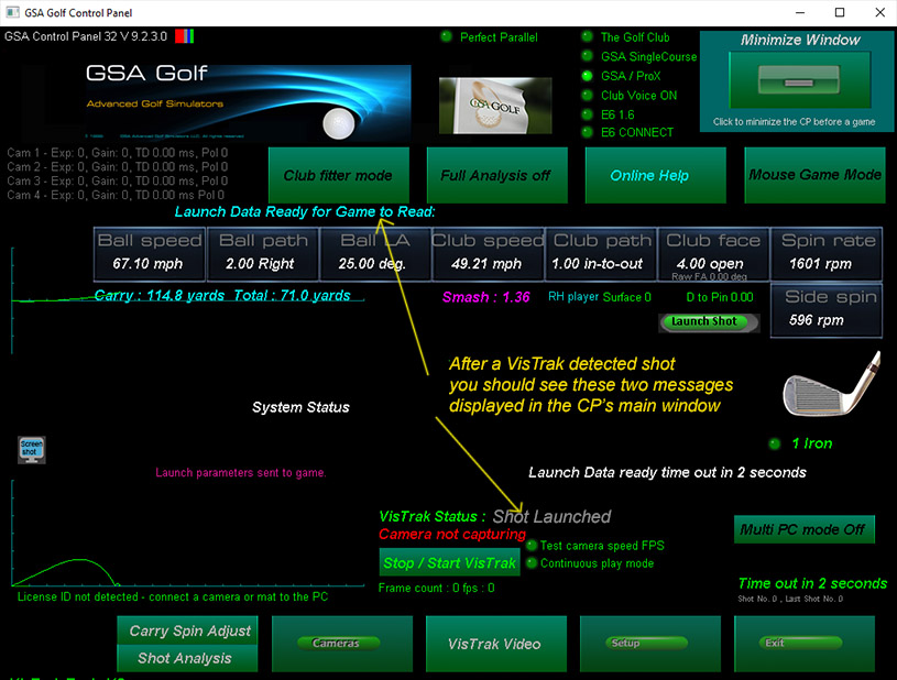
3. After the ball has been struck, the CP will send the shot data to the golf game software
and - after around 10 seconds - will automatically go back into "Looking for ball in Launch Zone" mode for the next shot .
![]()
CP controls
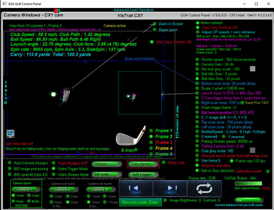
Camera window
The camera window displays the captured frame images.
There are up to 5 hi-resolution frame images.
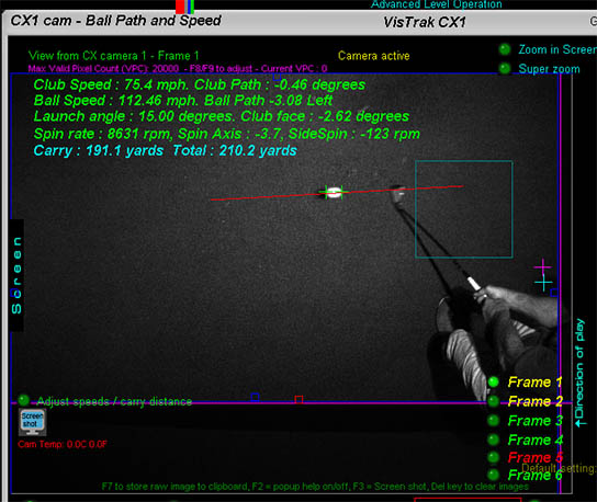
Frames 1 and 2 are images of the ball and club before ball strike.
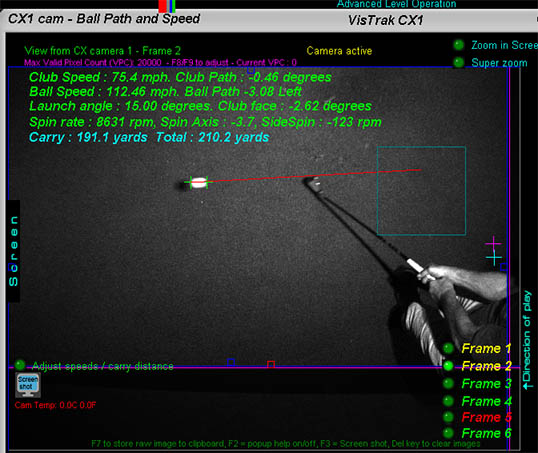
Frame 3 to 5 are images of the ball and club after ball strike.
You can select each frame individually or run the sequence of frames using the video control buttons.
Defaults button
Right click on this button to set all settings to their default values
Launch Zone
The Launch Zone is the designated area where the ball will be placed on the hitting surface.
You can set the position and size of the Launch Zone area using the keyboard arrow keys when "Launch Zone" is selected.
Hold the "ctrl" key down to adjust the size of the area with the arrow keys.
Top, bottom, left and right scan zone borders
Use these borders to adjust the valid FOV of the camera. All image processing will only be done within these borders.
Anything outside these borders (balls, objects etc) will be ignored.
Shutter speed and gain
Default values for the CX1 camera are 300us shutter speed and 34db gain
Adjusting these values will increase or decrease the brightness of the images
Min ball gray scale
This is the minimum gray scale (monochrome brightness) that the ball has to have in the images for the system to be able to detect the ball.
Default is 130.
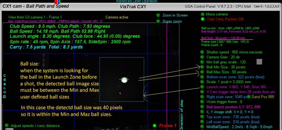
Ball min size, Ball max size
To help ensure that the object detected by the image processing is indeed a ball,
the object (or ball) must be no smaller than the user defined ball min size and no larger than the ball max size.
Set Scale button
Scale: 1 pixel
As the camera sees only pixels in the image, a pixel to real-world (mm) conversion factor is required.
To set the scale, place a ball on the floor, select Frame 1 and press the "Soft Trigger" button to grab a new image.
Ensure that the system has detected the ball (shown by 2 green cross hairs on either side of the ball)
and press the "Set Scale" button.
You may have to press the "Set Scale" button twice if at first the scaling factor couldn't be set.
Measure ball launch angle from ball image size.
When this option is switched ON, the system will compare
the size of the ball image in flight to the ball image size when the ball was on the floor or on the tee.
The ball image size variation is used to calculate the height of the ball and thus the LA (Launch angle) of the ball.
When switched OFF, the system estimate the LA from either the loft angle of the selected club or the user designated LA for the selected club.
Measure Club data
When this option is switched ON, the system will attempt to capture the club face angle,
club path and club speed from the club images before and after ball strike.
In order to capture club data, white tracking strips have to be applied to most of the clubs.
When switched OFF, club data will be derived from ball data.
Ball on floor detection
As the VisTrak CX camera has a very large FOV,
there is a great likelihood that balls from previous shots will still be lying around on the floor and be in the FOV of the camera.
When this option is switched ON, the system will detect these balls and eliminate them from the ball speed and path image processing.
If this option is switched OFF, then any balls on the floor that are in the valid FOV of the camera may interfere with image processing
and thus produce erroneous ball speed and path results.
Frame rate 290 fps
At full image resolution (1280 X 960 px) the frame rate of the camera is 160 fps.
A ball traveling at 150mph will move 3ft in each frame at this frame rate
If the "Frame rate 290 fps" option is set ON,
then the image resolution is halved to 640 X 480px but the rate rate increasing to 290 fps.
A ball traveling at 150mph will move 1.5ft in each frame at this frame rate
Note: after changing the frame rate, the CP has to be closed down and the camera unplugged.
Plug the camera back in and wait for the "device detected" sound from Windows and restart the CP
![]()
Adjusting measured ball speed and carry
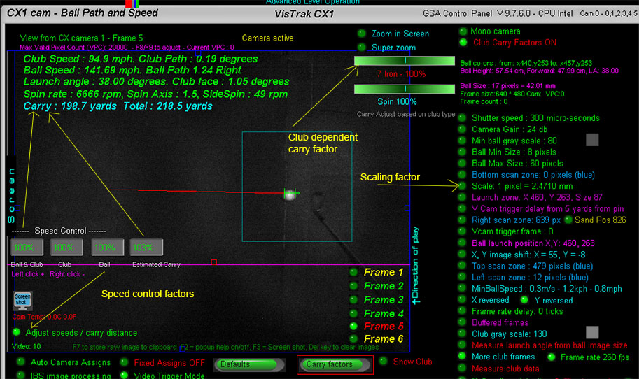
There are 4 main user adjustable factors that will greatly influence measured ball speed and thus carry.
1. Scaling factor
The scaling factor is used to convert measured distances in pixels to real world distances in meters (cm and mm)
Use the "Set scale" button to set the scale after the ball has been detected
The scaling factor is a global speed adjustment factor for all clubs
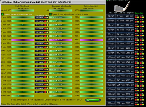
2. Club dependent carry factor
There is a separate club dependent speed control factor for every club.
Use the slider bar to adjust measured ball speed for a particular club.

3. Speed controls
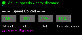
The speed controls are global speed adjustment factors for all clubs
Click the "Adjust speeds / carry distance" button to open the speed controls.
Left or right click to adjust the specific factor.
Note that the CP can only estimate carry.
The game software (TGC, E6 etc) is responsible for trajectory and carry calculations.
However, you can adjust the CP's estimated carry using the estimated carry speed factor
4. LA Speed adjust
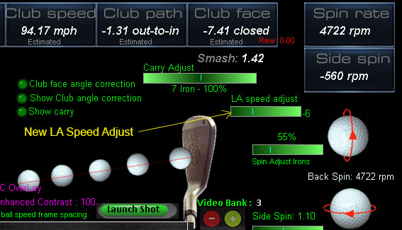
Auto LA ball speed adjustment for VisTrak Eagle and CX 1 systems based on launch angles.
i.e. for systems that are only measuring ball speed from an overhead single camera without any vertical launch angle information.
This factor will reduce (if minus) the measured ball speed based on launch angle (LA). i.e. the higher the LA, the more speed reduction is made.
The reason for this is to compensate for varying ball image sizes.
i.e. the higher the ball is in flight, the nearer the ball is to the overhead camera and thus the ball image size increases.
Without this adjustment, measured ball speeds will seem to increase along with the increasing LA.
![]()
Shot frames as viewed from the overhead camera
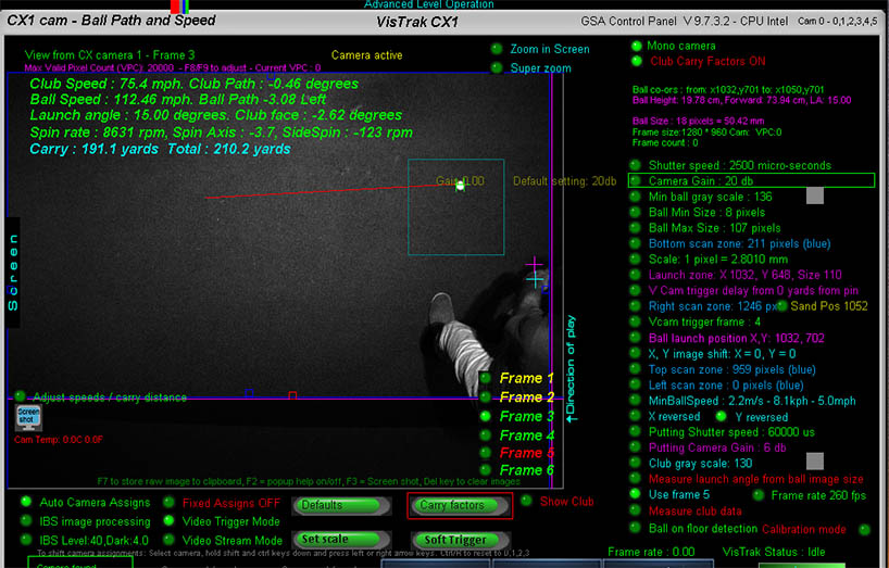
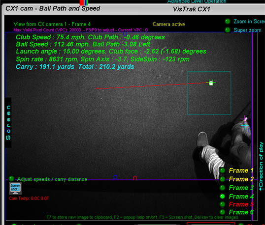
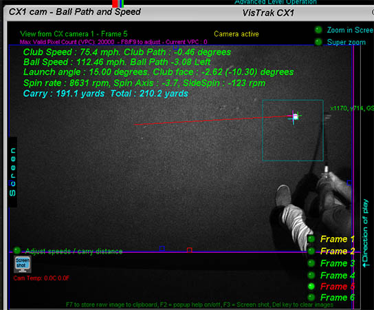
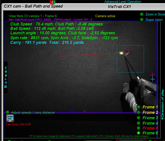
![]()
VisTrak CX Problem Solving
1. Camera not detected
Check the camera driver install page
2. Ball not detected

1. Check ball min size
Reduce to 7 pixels if ball appears small
2. Insufficient contrast or lighting
Ensure that you have sufficient IR LED lighting (2 to 4 Hi powered IR LED lights)
and light spread over the floor in the FOV of the camera,
Ensure flooring is low reflective and that all appears relatively dark in the camera images.
Adjust shutter speed and camera gain to obtain a good contrast between the ball and the flooring.
3. Incorrect ball speed
Ensure you are using the latest CX CP update
CX Control Panel update V 9.7.6.0
Set or Adjust Scale factor to change the global measured ball speed.
Use the club carry adjust slider bar to adjust club specific measured ball speed.
![]()

Add a second VisTrak CX camera for increased vertical launch angle (LA) measurement accuracy
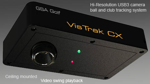
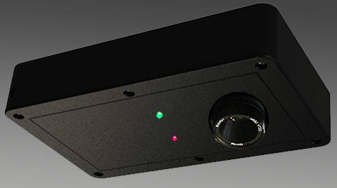
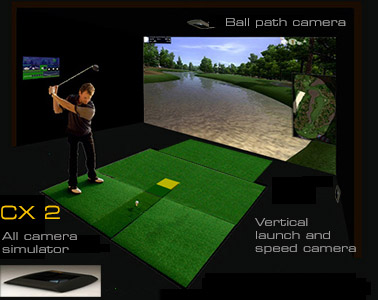
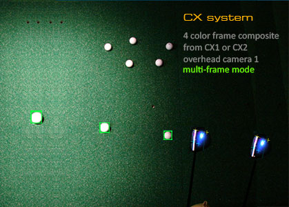
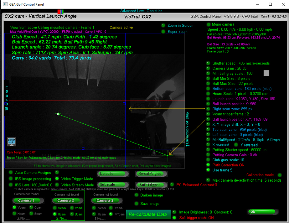
The add-on Vcam vertical launch angle camera is mounted on the far left or right side of the enclosure at floor level.
It thus views the ball in flight from the side.
The camera functions for both left and right handed players without having to move the camera.
instructions to follow ...
![]()
Warranty and Support